What is the reason for the warnings printed on gas pumps cautioning us not to get in and out of the car when we’re pumping gas? The reason is that cars pick up electrostatic charges as they run, and the car’s tires insulate that charge from the ground. Electrostatics is the study of electrical charges on objects at rest.
There are two fundamental charges: positive and negative. We know that similarly charged objects repel and oppositely charged objects attract. Besides this, objects that are neutral (i.e. objects with an equal amount of positive and negative charge) are attracted to both positive and negative objects. Why do we know this? Let’s first review the basic model of the atom.
The very center of the atom is a tiny concentrated region that contains positive particles (protons) and neutral particles (neutrons), called the nucleus. The number of protons in the nucleus uniquely determines what element it is. This number will not change unless a “drastic” nuclear event occurs (i.e. fission or fusion). In the large region of space around the tiny nucleus there is likelihood that you will find negative particles (electrons). In neutral atoms, the number of electrons equals the number of protons. In order for an object to gain a negative electric charge, it gains extra electrons. To pick up a positive charge, the object loses electrons. Thus, electrons are the “mobile fluid” responsible for charging objects. An object will always have the same amount of protons before and after gaining an electrostatic charge.
Some elements are naturally good conductors of electricity. Conductors are materials in which electrons flow easily from atom to atom. Metals are excellent examples of conductors. Dielectrics, or insulators, are materials in which the electrons are tightly bound to a particular nucleus. Rubber, plastic, and air are examples of good insulators. Under conditions with very high voltages, even insulators may have electrons travel throughout the material.
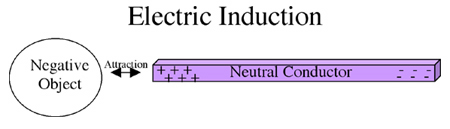
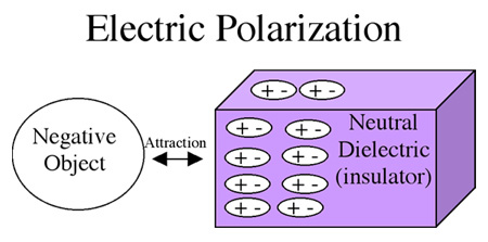
Why are neutral conductors and neutral insulators attracted to charged objects? The explanation is a little different for each. When a negatively charged object is brought near a conductor, the electrons in the conductor are repelled by the electrons in the charged object. The free electrons in the rod are forced to move to the opposite side of the rod, leaving the positive nuclei to attract the negative object. This process is called electric induction and is represented in the following diagram:
In an electrostatics experiment, two pieces of tape attract each other. The most you can conclude is that:
The correct answer is A. It is tempting to answer C because we know that oppositely charged objects attract, but that is not the only case in which we observe an attraction. Neutral objects also attract charged objects, so all we can confidently conclude in this question is that at least one of the pieces of tape is charged. The other piece of tape could be neutral or oppositely charged.
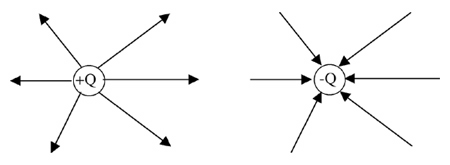
In the vicinity of charged objects, there exists an electric field in which other charged objects will experience forces. The charged objects have “lines of force” or “flux lines” emanating from them. The direction of the force exerted on a positive test charge placed near a charged object is shown by placing arrowheads pointing into the object to represent a negatively charged body, or arrowheads pointing out of the object if it is a positively charged body. For example, the first diagram below shows that a positive test charge is repelled from a positive central charge (+Q). The second diagram shows that the same positive test charge is attracted to a negative central charge (-Q).
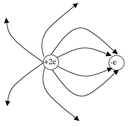
For example, what would the electric field pattern look like if two protons (+2e) were in the vicinity an electron (-e)? The following diagram will show the pattern:
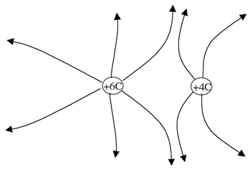
What do field lines look like in the vicinity of two repelling charges? For example, the following diagram shows the electric field pattern in the vicinity of a +6 Coulomb charge and a +4-Coulomb charge:
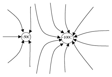
Now try sketching the electric field line pattern in the vicinity of a -50C and a -100C charge.
Previously we covered that work is done when forces displace objects. When this occurs energy is transferred from one storage mode into another. In this lesson, we will study how energy is transferred in electrical circuits caused by electromotive force.
Electrical circuits may be powered by a variety of energy sources. Here are a few examples of devices that serve as energy sources for circuits:
Each of these devices applies an electromotive force (EMF) that does the work on the electrons in the circuit to transfer energy.
The wires in a circuit provide a pathway for energy transfer. For example, using a simple circuit between a battery and a light bulb, the electrons within the circuit carry energy from the battery to the bulb. These electrons are never created nor destroyed during the process of transferring the chemical energy in the battery to radiant energy shining from the bulb. In a circuit powering an electric blanket, for example, electrical energy is transferred to heat energy.
The electromotive force (EMF) is the potential energy per unit charge that can be transferred to the electrons in a circuit. The units are “joules per coulomb,” which is defined to be a volt. The EMF is measured by finding voltage, or electric potential difference, across the two ends of the power supply when there are no electrons flowing. If current is running through the power supply, the voltage measurement is actually less than the EMF. Thus, the EMF is the maximum possible potential difference measured across a power source.
A 9.0-Volt battery establishes current in a simple circuit. Which of the following measurements are possible if a voltmeter is placed across the battery in the circuit?
The correct answer is A. The maximum possible voltage measurement is the EMF (9.0 Volts) and this is measured with no current in the battery. When current is flowing, the voltage drops because of the internal resistance of the battery. Therefore, 8.5 V is the only possible measurement in the options given.
Previously you have seen that an electromotive force is responsible for providing the potential to move electrons in a circuit. You also learned that electrons are charged particles that carry energy in a circuit. In this lesson, we will formally define the concept of electric current.
When there is a difference of pressure across the two sides of a water pipe, water will flow from a region of higher pressure to a region of lower pressure. Thus, water current is established in the pipe, and this current is measured in gallons per second. Likewise, when there is a difference of electric potential (voltage) across a wire, electrical current is established. Electric current (I) is a measure of the number of electrons (measured in Coulombs Q) that pass a point in a circuit over a certain amount of time (t). The equation is written like this:
I = Q / t
The units of electrical current are Coulombs per second which is defined as the Ampere (A).
Electrical current may be classified as “direct” or “alternating.” Direct current (DC) occurs when the electrons circulate in one direction throughout the circuit. Batteries naturally produce DC current. The electrons move quickly in a DC circuit, but the energy they carry is transmitted almost instantaneously throughout the circuit. Alternating current (AC) occurs when the electrons vibrate back and forth at a particular frequency. Generators naturally produce AC current. As we shall see in a later lesson, AC current is typically used when a significant amount of energy is transferred through long distances.
25 Coulombs of electrical charge moves through a cross-section of wire every 5 seconds. What is the current in the wire?
The correct answer is B and is calculated as follows: I = Q / t = (25 C) / (5 s) = 5 C / s = 5 A
When electrons move in an electric circuit the parts of the circuit resist the movement of the electrons. This property in an electric circuit is called resistance. Some electrical devices allow electrical current to flow easily through them. We say that these devices have a low resistance to the flow of electrons. Devices with a high resistance, on the other hand, resist the flow of current. These devices require a power source with a larger voltage to establish the same current as a low resistance device. Consider a simple circuit consisting of a battery and some device (like a light bulb). As the voltage of the battery increases, the current running through the circuit will increase. The resistance of a device is the ratio of the voltage across it to the current running through it as demonstrated on the following graph:
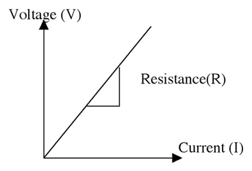
y = mx + b
V = R I + 0
V = I R
where V = voltage, I = current, and R = resistance.
The measurement unit of resistance is the ohm ( Ω ) and is defined as the ratio of volts to amps.
What is the resistance in the 30 Amp heating coil of a coffee maker that operates on a 120 V circuit?
The correct answer is B. The numbers are plugged into Ohm’s law as follows: R = V/I = (120 V) / (30 Amp) = 4.0 ohms.
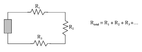
One way to increase the electrical resistance is to put a string of devices in series along the same electrical path. The total resistance of the path is the sum of all the individual resistances in the path as follows:
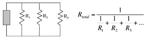
Circuits can also be wired in parallel where there are multiple paths for the electrons to take. With the extra pathways, the resistance of the circuit drops as follows:
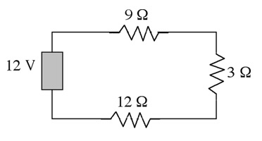
Most electrical devices are a combination of series and parallel devices. For example, consider the following combination circuit:
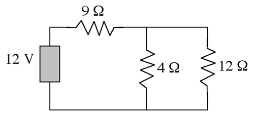
Thus, applying Ohm’s law, the total current drawn by the circuit is:
I = V / R total = (12V) / 12 Ω ) = 1 A
The circuit shown below has a total resistance of 24 Ω. What is the total current drawn by the battery?
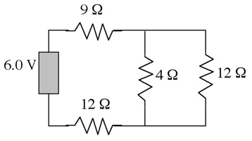
The correct answer is A. Applying Ohm’s Law to the circuit, we obtain the current by dividing the voltage of the power supply by the total resistance:
I=V/R total = (6.0V)/(24 W ) = 0.25 A
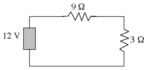
To calculate the total resistance, first determine the resistance of the 4 W and 12 W resistors in parallel. This is 3 W as shown earlier in this lesson. Now the circuit looks like the following series circuit:
R total = 9 + 3 + 12 = 24 W
Previously we covered that electrical energy is delivered via direct current (DC) or alternating current (AC). In this lesson, we will study the applications that are appropriate for DC and AC.
When current flows through a wire, the wire will heat up because of the wire’s resistance. For applications that require low current flow through short distances, the amount of heating in the wires is negligible. Batteries produce DC and are used to deliver energy through short distances in circuits.
When distributing large amounts of energy to electrical power grids, high currents are needed for energy transmitted at common household voltages (120V). The amount of line heating in the wires is prohibitive with these large currents, costing millions of dollars per mile of wire every hour just to power a medium-sized city. When AC is used, however, step-up transformers increase the transmitting voltage and drop the current to levels where the energy loss due to line heating is acceptable. At the household level, step-down transformers drop the voltages back down to 120V and raise the current to levels demanded by the consumer. Transformers only operate with AC current.