When light hits a boundary between different media, three phenomena occur:
Instead of focusing on the crests and troughs, we show the path of light waves with rays. The ray that strikes a boundary is called the incident ray. The ray that bounces back into the original medium is called the reflected ray. Both rays make equal angles with respect to a line perpendicular to the surface (the “normal line”), as shown in the following figure:
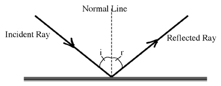
The law of reflection applies to all surfaces: shiny, curved, or rough. When light rays hit rough surfaces, though, the normal line direction varies for each part of the surface and the light diffuses in all directions.
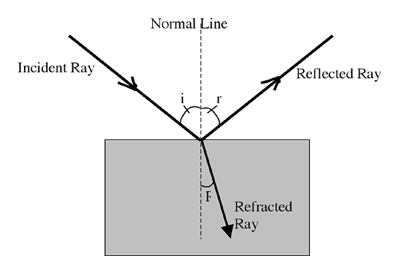
What happens when light hits an optically transparent medium? Some of the light energy will always reflect back into the original medium. But much of the light and energy usually enters the new medium. Depending on the optical density of that medium the light will “bled” or refracts a slight amount from its original path, or it may refract quite a bit from its original path. If the new medium slows down the light we say that the medium has a higher optical density. When this occurs, the light bends to a smaller refraction angle (R) relative to the normal line as shown in the following diagram:
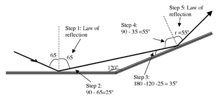
What is the final angle of reflection (r) in the following figure (not to scale)?
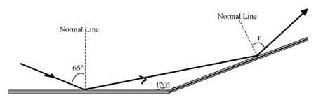
The correct answer is B; r = 55°. The steps are as follows:
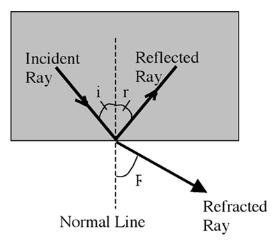
When light rays attempt to exit a medium with high optical density, refraction may not occur. Rather, the energy may be completely reflected back into the denser medium. This phenomenon is called total internal reflection (TIR). What determines when TIR occurs? It depends on the “critical angle” of the materials involved. Every pair of transparent materials has a unique critical angle depending on their optical densities. The following table lists some common critical angles:
| Light starting in… | Light trying to enter… | Critical angle |
|---|---|---|
| Water | Air | 49° |
| Glass | Air | 41° |
| Glass | Water | 61° |
| Diamond | Air | 24° |
Notice that the critical angle is only relevant when light starts in an optically dense material and attempts to move into a less dense material. The critical angle is used with following logic to determine if TIR occurs at a boundary:
For example, when light attempts to exit a diamond into air at an angle of 20 degrees, it will partially reflect and partially refract because its incident angle is less than the critical angle of 24 degrees. When light tries to exit at 30 degrees however, it will totally reflect because its angle is greater than the critical angle.
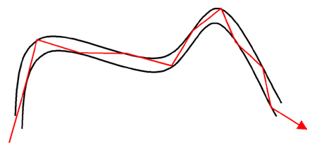
Total internal reflection is used in optical fibers to send information efficiently from one location to another. The following diagram shows the total internal reflections that occur through a light pipe:
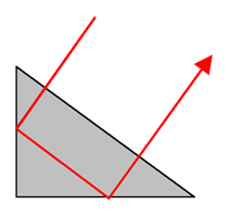
The phenomena of total internal reflection is also used to reflect light in prisms as follows:
When a light ray attempts to move from glass into air at an incident angle of 45 degrees, which of the following phenomenon occurs? (Note: the critical angle for glass/air is 41 degrees.)
The correct answer is B because the incident angle is greater than the critical angle.
Previously we learned that different colors of light have different frequencies, where red light has the lowest frequency and violet light has the highest frequency. In this lesson, we will study how light of various frequencies refract differently in glass.
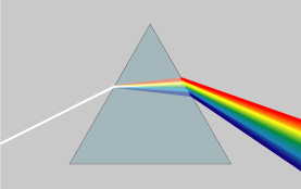
When white light hits a glass prism just right, the light exiting the prism will bend into a full rainbow of colors through the process of dispersion. This occurs because high-frequency visible light tends to interact with the glass molecules more than the low frequencies. The result looks like this:
Dispersion is responsible for rainbows. If sunlight hits water droplets in the air just right, the droplets behave like little prisms and disperse and reflect a rainbow of light toward the observer.
Light can also be dispersed using prism spectrometers (a.k.a. spectroscopes). These devices analyze visible light so the observer can identify the colors (frequencies) that are present in a particular light source.
Previously we learned that transverse waves vibrate the medium at right angles to the motion of the wave energy. Longitudinal waves, on the other hand, vibrate the medium parallel to the direction of wave motion through compressing the medium. Since light radiation consists of electric and magnetic vibrations that are perpendicular to the direction of wave motion, light is classified as a transverse wave. In this lesson, we will study the phenomenon of light polarization that provides evidence that light is a transverse wave.
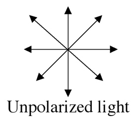
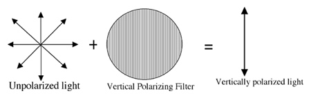
The vibrations that produce sunlight are in random directions. Likewise, the electron vibrations in candle flames and the filaments of light bulbs are also in all directions. These sources produce unpolarized light because the transverse vibrations that produce the light are in many directions. Imagine looking at a beam of light coming straight toward you. The following diagram represents unpolarized transverse light waves vibrating horizontally, vertically, and at angles:
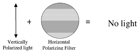
When vertically polarized light attempts to get through a horizontal filter, the intensity drops to zero:
A beam of light moves through a horizontal and then a vertical polarizing filter. The intensity of the light emerging from the combination is
The correct answer is A. Only horizontally polarized light is able to get through the first filter. Since the second filter is vertical, the horizontal light is completely absorbed.
Previously we have seen that waves are energy. When a wave meets a wave, the waves pass right through each other. When they occupy the same space, they interfere with one another. If identical parts of the waves interfere (e.g. a crest meets a crest), the disturbance grows due to constructive interference. If opposite parts of the wave interfere, the disturbance is reduced through destructive interference. In this lesson, we will study different ways that light waves interfere and how this provides evidence that light behaves like a wave.
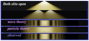
Historically, there was much debate about whether light behaves like a wave or like a particle. In fact, the scientific community generally believed that light behaved as a particle up until 1801. In that year, Thomas Young performed an experiment by sending monochromatic light (one frequency) through two tiny openings. When the light hits a screen, it showed multiple bright areas of constructive interference as well as dark areas of destructive interference. Two-slit interference is shown in the following diagram:
When light hits soap bubbles or a film of gasoline on water, a beautiful rainbow of colors often results. Why does this occur? To explain this, we must realize that the light is actually reflecting from two surfaces. In the gasoline example, the light reflects from the surface of the gasoline as well as the water. The reflected rays may interfere constructively or destructively depending on their frequency (color). As the thickness of the film varies, certain colors interfere constructively and these are the ones that we see. This phenomenon is called thin film iridescence.
Young’s famous two-slit experiment demonstrates which of the following properties of light?
The correct answer is C. The two-slit experiment shows interference patterns from light. Interference is a phenomenon associated with waves.
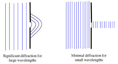
When waves hit an opening, they tend to fan out in many directions. Diffraction is the bending of waves around obstacles. The amount of diffraction depends on the size of the opening as in the following figure:
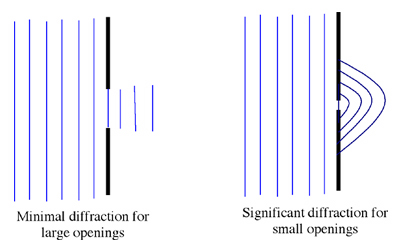
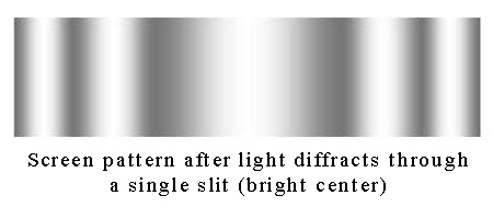
Since light is a wave, it also diffracts. If light goes through a big opening like a window, the light does not diffract significantly. This is because the wavelength of light is too small compared to the width of the opening. If light travels through a tiny slit, it spreads out significantly. So one might expect to only see a bright center pattern fading to the edges. But besides this pattern, the following figure shows interference patterns similar to those seen in Young’s two-slit experiment.
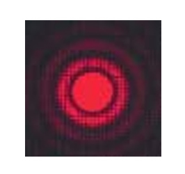
Laser light diffraction pattern through circular aperture
Light diffraction distorts images of very tiny objects like those on microscope slides. Tiny objects have dimensions that are similar to the wavelength of light. This results in significant bending around the objects and their images are not clearly seen. In order to see tiny objects clearly, they must be illuminated with wavelengths that are significantly shorter than light. Electron beams, like those used in electron microscopes, have tinier wavelengths than light and enable scientist to observe very small objects. For each source of illumination, diffraction sets a limit on the resolution of images.
In which of the following cases is the amount of light diffraction the most significant?
The correct answer is A. The amount of wave diffraction depends on the ratio of wavelength to the size of the opening.
Previously you have learned that when light hits a medium with a different optical density, the beam refracts and bends to different angles. In this lesson, we will study the images produced when light refracts through lenses.
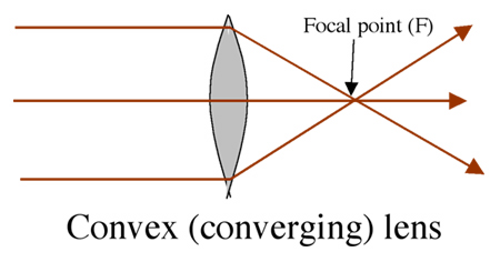
Lenses are used in a variety of applications, including glasses, microscopes, telescopes, and the human eye. There are two types of lenses: convex or concave. A convex lens (or converging lens) is thicker in the middle and takes parallel light rays and focuses them to a common point, called the focal point (F)
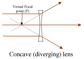
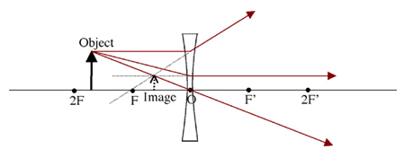
A concave lens (or diverging lens) is thinner in the middle and takes parallel rays of light and spreads them apart. The diverging rays appear to originate from the focal point (F), sometimes called a virtual focal point because the rays don’t actually go through this point.
An image’s characteristics depend on the type of lens used as well as the location of the object with respect to the lens.
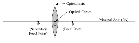
To determine the location of images, lens ray diagrams are used. The following terms are used in the ray diagram rules:
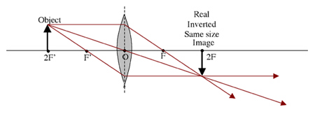
Let’s begin by looking at objects that are located beyond two focal lengths from the lens and apply the three rules above.
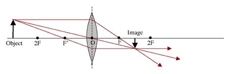
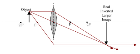
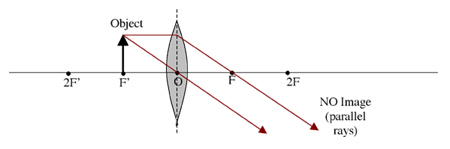
Here are some other diagrams with the object at different locations:
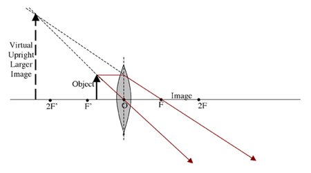
The last ray diagram above shows how in the formation of a virtual image the real light rays do not intersect. To see the image, it must be viewed by looking back through the lens, giving the illusion of a magnified image. This is how a simple magnifying lens works, but only if the object is within one focal length of the lens. An example of convex lenses would be the ones used as reading glasses to correct farsightedness.
The ray rules are almost identical for concave (diverging) lenses:
The table below summarizes the images formed by lenses:
| Lens Type | Object Distance from Lens | Image Type | Image Orientation | Image Size | Possible Applications |
|---|---|---|---|---|---|
| Convex | Beyond two focal lengths | Real | Inverted | Smaller | Camera, Human eye |
| Convex | At two focal lengths | Real | Inverted | Same Size | Copy machine (100%) |
| Convex | Between 1 & 2 focal lengths | Real | Inverted | Larger | Movie Projector |
| Convex | At one focal length | None | None | None | Spot lights |
| Convex | Between lens and focal point | Virtual | Upright | Larger | Reading Glasses |
| Convex | Anywhere | Real | Upright | Smaller | Distance Glasses |
A copy machine is used to make an image that is 50% of the original. What type of lens may be used to project the right size image to copy?
The correct answer is A. Real light rays must be focused to a point in order to burn an image onto the copy. Only convex lenses are capable of producing real images.
A copy machine is used to make an image that is 50% the size of the original. How far from the lens should the original be placed?
The correct answer is D. In order to get a smaller image, the original must be beyond two focal lengths from the lens.
Lenses (as well as mirrors) are used in combination to produce significant magnifications. The compound microscope, for example, takes the rays coming from a microscope slide and refracts them through a convex lens (the objective lens) to produce a real, inverted, larger image. This image is viewed through a second convex lens (the eyepiece lens) that magnifies it even more. Compound microscopes have 2 or more lenses, depending on the resolution needed.
Astronomical refracting telescopes usually use two convex lenses in combination. The light from distant planets is refracted to a real, smaller, inverted image through the first lens (the objective lens). The second lens (the eyepiece lens) magnifies this image. The image coming through the two-lens system is inverted relative to the original objects.
Mirrors are also used in combination with lenses to produce images. Sir Isaac Newton designed the first reflecting telescope in 1668. The Newtonian reflecting telescope uses a concave mirror to focus the light from distant starts to a diagonal plane mirror as shown in the diagram below. The plane mirror reflects the rays though a hole in the side of the telescope into an eyepiece lens. Because large diameter mirrors can be supported better than lenses, these telescopes gather more light than astronomical telescopes.
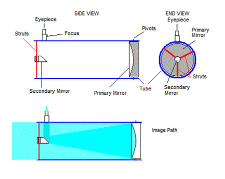
Newtonian telescope diagram
The human eye can also be visualized as a two-lens system. The front part of the eye, called the cornea, is where most of the refraction occurs. Significant bending occurs here because light slows down significantly as it enters the cornea. After the light bends through the cornea, it hits the lens. The lens makes fine adjustments in order to focus the light on the retina. The retina sends the image information to the brain for processing.
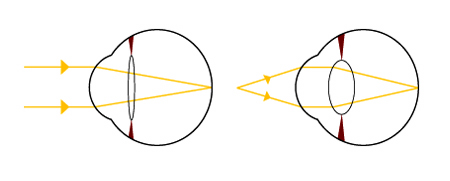
Human eye lens